ADC USING SUCCESSIVE-APPROXIMATION
A successive approximation ADC
is a type of analog-to-digital converter that converts a continuous
analog waveform into a discrete digital representation via a binary
search through all possible quantization levels before finally
converging upon a digital output for each conversion.
BLOCK DIAGRAM:
 | |||||
| Fig 1: Successive Approximation ADC Block Diagram |
Block Explanation:
- A sample and hold(S/H) circuit to acquire the input voltage (Vin).
- An analog voltage comparator that compares Vin with the output of the internal DAC and the result of the comparison outputs is given to the successive approximation register (SAR).
- A successive approximation register subcircuit designed to supply an approximate digital code of Vin to the internal DAC.
- An internal reference DAC that, for comparison with V, supplies the comparator with an analog voltage equal to the digital code output of the SARin.
Using
741 om-amp to do the comparator operation, the op-amp contain two input
one is inverter i/p(-) and another is non inverter i/p(+) see (fig 2),
 | |||||
| fig 2: Comparator. |
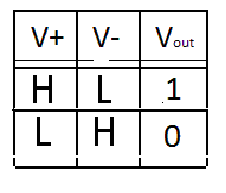
It compares two voltages or currents and outputs is digital logic as show in table. It has two analog input terminals  and
 and one binary digital output
 . The output is ideally( either high or low),
and and one binary digital output . The output is ideally( either high or low),